Seamlessly Connect Your RFID Reader to Arduino: A Step-by-Step Guide
This article provides a comprehensive guide on how to connect an RFID (Radio-Frequency Identification) reader to your Arduino, enabling you to build various interactive and automated projects. While the specific wiring can vary based on your RFID module, the core principles remain consistent. We will break down the common steps and considerations, focusing on the highly popular RC522 module as a practical example, followed by general advice applicable to other RFID readers. By the end of this guide, you will have a clear understanding of the components, wiring, and code necessary to successfully implement an RFID system with your Arduino.
Connecting an RC522 RFID Module to Arduino (Common Example)
The RC522 RFID module primarily communicates with your Arduino board via the SPI (Serial Peripheral Interface) protocol. This section will detail the specific requirements and step-by-step instructions for wiring and programming the RC522.
What You'll Need:
- Arduino Board: Any compatible board such as an Arduino Uno, Nano, or Mega.
- MFRC522 RFID Reader Module: This is the specific RFID reader we will focus on for the practical example.
- Jumper Wires: Male-to-Female jumper wires are essential for securely connecting the module's pins to the Arduino.
- Arduino IDE: Ensure you have the Arduino Integrated Development Environment installed, along with the
MFRC522library (installable viaSketch > Include Library > Manage Libraries...).
RC522 Pinout (Common):
Your RC522 module will typically feature several pins, each serving a distinct function in its communication and operation:
- SDA (or SS): Slave Select / Chip Select pin, used to enable or disable the module for SPI communication.
- SCK: Serial Clock pin, providing the clock signal for data transfer.
- MOSI: Master Out Slave In, the data line from the Arduino (Master) to the RFID module (Slave).
- MISO: Master In Slave Out, the data line from the RFID module (Slave) to the Arduino (Master).
- IRQ: Interrupt Request (often optional for basic applications).
- GND: Ground connection, essential for completing the circuit.
- RST: Reset pin, used to reset the module.
- VCC: Power supply pin (typically 3.3V).
Wiring (RC522 to Arduino Uno Example):
For Arduino Uno boards, the dedicated SPI digital pins are fixed. However, the SDA and RST pins can be connected to any available digital pins you choose, which you will then define in your sketch.
Here’s a typical wiring configuration for an RC522 module with an Arduino Uno:
| RC522 Pin | Arduino Uno Pin | Description |
|---|---|---|
| VCC | 3.3V | Power supply for the RC522 module. |
| RST | Digital Pin 9 | Reset pin (user-definable digital pin). |
| GND | GND | Ground connection. |
| IRQ | (Not Connected) | Interrupt pin (optional for this basic example). |
| MISO | Digital Pin 12 | Master In Slave Out (Arduino's dedicated SPI MISO). |
| MOSI | Digital Pin 11 | Master Out Slave In (Arduino's dedicated SPI MOSI). |
| SCK | Digital Pin 13 | Serial Clock (Arduino's dedicated SPI SCK). |
| SDA (SS) | Digital Pin 10 | Slave Select / Chip Select (user-definable digital pin). |
Important Note on VCC: It is crucial to note that most RC522 modules operate at 3.3V. While some versions might tolerate 5V, it is significantly safer and highly recommended to connect the VCC pin to your Arduino's 3.3V output to prevent potential damage to the module. Always refer to your specific module's datasheet for its voltage requirements.
Arduino Code Example - RC522
Once your RC522 module is correctly wired to your Arduino, the next step is to upload the necessary code. The MFRC522 library simplifies interaction with the reader. The following example demonstrates how to read the Unique Identifier (UID) of an RFID card.
#include <SPI.h> // Include the SPI library for communication with the RC522
#include <MFRC522.h> // Include the MFRC522 library for RFID reader functions
#define SS_PIN 10 // Define the Slave Select (SS) pin for the RC522, connected to Arduino Digital Pin 10
#define RST_PIN 9 // Define the Reset (RST) pin for the RC522, connected to Arduino Digital Pin 9
// Create an instance of the MFRC522 class, passing the SS and RST pins
MFRC522 mfrc522(SS_PIN, RST_PIN);
void setup() {
Serial.begin(9600); // Initialize serial communication at 9600 baud rate for debugging
SPI.begin(); // Initialize the SPI bus for communication
mfrc522.PCD_Init(); // Initialize the MFRC522 RFID reader module
// Print a message to the serial monitor indicating readiness
Serial.println("Approximate your card to the reader...");
Serial.println();
}
void loop() {
// Check if a new card is present. If not, return and continue looping.
if ( ! mfrc522.PICC_IsNewCardPresent()) {
return;
}
// Select one of the new cards. If no card is selected, return.
if ( ! mfrc522.PICC_ReadCardSerial()) {
return;
}
// Display the Unique Identifier (UID) of the detected card
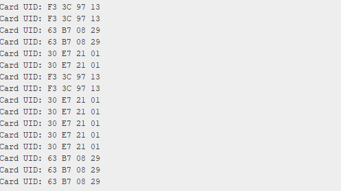
Serial.print("Card UID:");
// Iterate through each byte of the UID
for (byte i = 0; i < mfrc522.uid.size; i++) {
// Format the output: add a leading "0" if the byte is less than 0x10 (hex 16)
Serial.print(mfrc522.uid.uidByte[i] < 0x10 ? " 0" : " ");
Serial.print(mfrc522.uid.uidByte[i], HEX); // Print the byte in hexadecimal format
}
Serial.println(); // Move to the next line for the next reading
// Halt the PICC (Proximity Integrated Circuit Card) to prevent multiple reads of the same card
mfrc522.PICC_HaltA();
}
This code initializes the RFID reader and continuously checks for new cards. When a card is detected, it reads and prints its unique ID (UID) to the Serial Monitor. This UID can then be used in your projects for identification, access control, or other applications.
General Steps for Connecting Any RFID Module
While the RC522 is a popular choice, there are various RFID modules available, each with its own specifications. The following general steps will help you connect almost any RFID module to your Arduino:
- Identify Your RFID Module: Before starting, accurately identify the model number of your RFID module (e.g., PN532, EM-18, RDM6300). This information is critical as it dictates the communication protocol and voltage requirements.
- Find the Module's Pinout: Search online for the specific "[Your RFID Module Model] pinout" or its datasheet. This will provide a diagram or table detailing the function of each pin (e.g., VCC, GND, TX, RX, SDA, SCL, SCK, MOSI, MISO, SS, RST).
- Understand the Communication Protocol: RFID modules typically use one of three main communication protocols:
- SPI (Serial Peripheral Interface): Fast and efficient, commonly used by modules like the RC522. It uses dedicated pins: SCK (Serial Clock), MOSI (Master Out Slave In), MISO (Master In Slave Out), and a Chip Select (SS/SDA) pin.
- I2C (Inter-Integrated Circuit): Uses only two pins, SDA (data) and SCL (clock), making wiring simpler, especially for multiple I2C devices. Modules like the PN532 often use I2C.
- UART (Universal Asynchronous Receiver/Transmitter) / Serial: Uses TX (Transmit) and RX (Receive) pins. It's straightforward to use but generally slower than SPI or I2C. Modules like the EM-18 often use UART.
- Check Voltage Requirements: Most RFID modules operate at either 3.3V or 5V. Always connect the VCC pin to the correct voltage supply on your Arduino. Connecting a 3.3V module to a 5V supply can cause irreversible damage. If your module requires a voltage not directly available from your Arduino, you may need a voltage regulator.
- Wire the Module to Arduino: Connect the power pins (VCC to Arduino's 3.3V/5V and GND to Arduino's GND) first. Then, connect the communication pins according to the identified protocol. For SPI, use your Arduino's dedicated SPI pins. For I2C, use A4 (SDA) and A5 (SCL) on Uno/Nano boards. For UART, you can use Digital 0 (RX) and Digital 1 (TX), or for greater flexibility, employ the
SoftwareSeriallibrary with other digital pins. - Install Necessary Arduino Libraries: Most RFID modules are supported by dedicated Arduino libraries that simplify their use. Open your Arduino IDE, go to
Sketch > Include Library > Manage Libraries..., search for your module (e.g., "PN532," "RFID"), and install the recommended library. - Upload Example Code: Once the library is installed, navigate to
File > Examplesin the Arduino IDE and select an example sketch provided by the library. Crucially, adjust any pin definitions in the example code to match how you have wired your specific module to the Arduino. Then, upload the modified code to your Arduino board. - Test Your Setup: After uploading the code, open the Serial Monitor in the Arduino IDE (found under
Tools > Serial Monitor). Ensure the baud rate in the Serial Monitor matches theSerial.begin()speed in your code (e.g., 9600 baud). Swipe an RFID card or tag over the reader. If everything is connected and coded correctly, you should see output in the Serial Monitor, typically displaying the UID of the card or tag.
Troubleshooting or Advanced Tips
If you encounter issues during the setup, consider these common troubleshooting steps:
- Double-Check Wiring: Incorrect connections are the most frequent cause of problems. Carefully review your wiring against the pinout diagrams.
- Verify Voltage: Confirm that your RFID module is receiving the correct voltage (3.3V or 5V) as specified by its manufacturer.
- Library Compatibility: Ensure the installed Arduino library is compatible with your specific RFID module. Some modules may have multiple libraries available, and not all are universally compatible.
- SPI/I2C/UART Conflicts: If you're using multiple devices on the same communication bus (e.g., multiple SPI devices), ensure their Chip Select (SS) pins are correctly managed to prevent conflicts.
- Interference: RFID readers can be sensitive to electromagnetic interference. Try to operate the reader away from large metal objects or strong electrical fields.
- Card Compatibility: Ensure your RFID tags/cards are compatible with your reader's frequency (e.g., 13.56 MHz for RC522).
For advanced applications, consider exploring:
- Writing Data to Tags: Many RFID modules support writing data to compatible tags, not just reading their UIDs.
- Encryption and Security: For secure applications, research how to implement encryption methods with your RFID system.
- Integration with Other Sensors/Actuators: Combine your RFID system with relays, LEDs, displays, or other sensors to create more complex and functional projects.
Summary
Connecting an RFID reader to your Arduino opens up a world of possibilities for automation, security, and interactive projects. By understanding the specific requirements of your chosen module, diligently following the wiring instructions, and utilizing the appropriate Arduino libraries and code, you can successfully implement an RFID system. Whether you're building a simple access control system or a complex inventory management solution, the foundation laid in this guide will prove invaluable.
(Also, check out our guide on: [Internal Link to related article, e.g., "Getting Started with Arduino Basics"])
Frequently Asked Questions (FAQ)
Question 1: Can I use a 5V RFID module with a 3.3V Arduino? Answer 1: While possible, it requires a logic level shifter to convert the 5V signals from the module to 3.3V for the Arduino, and vice versa. Directly connecting a 5V module to a 3.3V Arduino's data pins without level shifting can damage the Arduino.
Question 2: Why isn't my RFID reader detecting cards? Answer 2: Common reasons include incorrect wiring, using the wrong Arduino digital pins for SPI/I2C/UART, issues with the installed library, or the RFID tag/card not being compatible with your reader's frequency. Double-check all connections and code.
Question 3: What is the difference between SPI, I2C, and UART for RFID modules? Answer 3: These are different communication protocols. SPI is generally the fastest and uses four wires (SCK, MOSI, MISO, SS). I2C uses two wires (SDA, SCL) and is good for connecting multiple devices to the same bus. UART (Serial) uses two wires (TX, RX) and is simpler but often slower for data transfer. The choice depends on the module and your project needs.
Question 4: Do I need an external power supply for my RFID module? Answer 4: For most small RFID modules like the RC522, the power supplied by the Arduino's 3.3V or 5V pin is sufficient. However, larger or more powerful RFID readers might require an external power supply to ensure stable operation.
Comments (0)
No comments yet. Be the first to comment!
Leave a Comment