Raspberry Pi Traffic Light with LCD Display – Beginner Project
Introduction
This tutorial will guide you through building a fully functioning traffic light system using a Raspberry Pi. It features Red, Yellow, and Green LEDs, all synchronized with an I2C LCD display that shows the current phase and a live countdown.
Perfect for beginners who want to learn GPIO pin control, timing, and I2C LCD communication using Python.
What You’ll Need
| Component | Quantity |
|---|---|
| Raspberry Pi (4 or 5) | 1 |
| Red, Yellow, Green LEDs | 1 each |
| 330Ω Resistors | 3 |
| Breadboard | 1 |
| Jumper Wires | Several |
| I2C 16x2 LCD Display | 1 |
| I2C LCD Backpack (usually built-in) | ✅ |
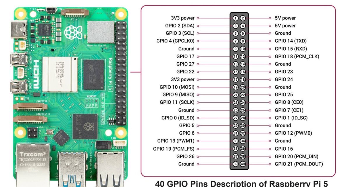
Wiring the Circuit
| LED | GPIO Pin | Physical Pin |
|---|---|---|
| Red | GPIO 17 | Pin 11 |
| Yellow | GPIO 27 | Pin 13 |
| Green | GPIO 22 | Pin 15 |
| GND | — | Pin 6 |
| LCD SDA | — | Pin 3 (GPIO 2) |
| LCD SCL | — | Pin 5 (GPIO 3) |
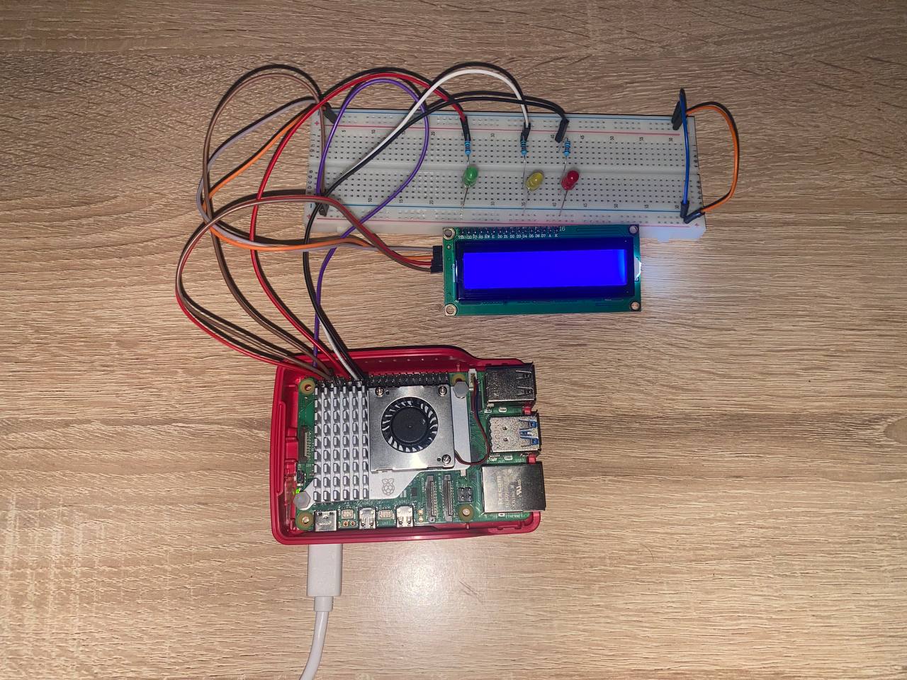
Use a 330Ω resistor on each LED’s long leg (anode). Connect the short leg to ground.
To check your LCD’s I2C address:
sudo apt install -y i2c-tools
i2cdetect -y 1
Usually, the address is 0x27 or 0x3F.
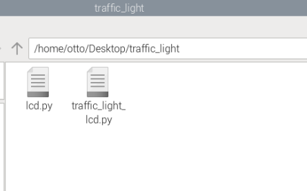
Python Code
Save this as traffic_light_lcd.py:
import RPi.GPIO as GPIO
import time
from smbus2 import SMBus
from lcd import LCD  # Make sure lcd.py is in the same directory

# GPIO Pins
RED = 17
YELLOW = 27
GREEN = 22

# Setup GPIO
GPIO.setmode(GPIO.BCM)
GPIO.setup([RED, YELLOW, GREEN], GPIO.OUT)

# Setup LCD
bus = SMBus(1)
lcd = LCD(bus)

def display_phase(led_pin, label, duration):
    """Turn on LED, update LCD, countdown, and turn off"""
    GPIO.output(led_pin, True)
    for i in range(duration, 0, -1):
        lcd.display(label, f"Time: {i}s")
        time.sleep(1)
    GPIO.output(led_pin, False)

def traffic_light_cycle():
    while True:
        display_phase(GREEN, "GO", 5)
        display_phase(YELLOW, "WAIT", 2)
        display_phase(RED, "STOP", 5)

try:
    traffic_light_cycle()

except KeyboardInterrupt:
    print("Exiting...")

finally:
    lcd.clear()
    GPIO.cleanup()
lcd.py Driver File
Create a file called lcd.py in the same directory:
import smbus2
import time

class LCD:
    def __init__(self, bus, addr=0x27):
        self.bus = bus
        self.addr = addr
        self.backlight = 0x08
        self.EN = 0b00000100
        self.RS = 0b00000001
        self.init_display()

    def write_byte(self, data):
        self.bus.write_byte(self.addr, data | self.backlight)
        time.sleep(0.0005)

    def toggle_enable(self, data):
        self.write_byte(data | self.EN)
        time.sleep(0.0005)
        self.write_byte(data & ~self.EN)
        time.sleep(0.0001)

    def write_command(self, cmd):
        self.write_4bits(cmd & 0xF0)
        self.write_4bits((cmd << 4) & 0xF0)

    def write_char(self, charvalue):
        self.write_4bits(charvalue & 0xF0, True)
        self.write_4bits((charvalue << 4) & 0xF0, True)

    def write_4bits(self, data, char_mode=False):
        bits = data | self.backlight
        if char_mode:
            bits |= self.RS
        self.write_byte(bits)
        self.toggle_enable(bits)

    def init_display(self):
        self.write_4bits(0x30)
        time.sleep(0.005)
        self.write_4bits(0x30)
        time.sleep(0.001)
        self.write_4bits(0x30)
        time.sleep(0.001)
        self.write_4bits(0x20)

        self.write_command(0x28)
        self.write_command(0x08)
        self.write_command(0x01)
        time.sleep(0.002)
        self.write_command(0x06)
        self.write_command(0x0C)

    def clear(self):
        self.write_command(0x01)
        time.sleep(0.002)

    def set_cursor(self, line, position):
        pos = position + (0x80 if line == 0 else 0xC0)
        self.write_command(pos)

    def display(self, line1="", line2=""):
        self.clear()
        self.set_cursor(0, 0)
        for char in line1.ljust(16)[:16]:
            self.write_char(ord(char))
        self.set_cursor(1, 0)
        for char in line2.ljust(16)[:16]:
            self.write_char(ord(char))
What You Learn
- Using GPIO to control hardware
- Controlling a 16x2 LCD via I2C
- Python scripting with loops and timers
- Synchronizing display output with physical actions
Conclusion
This traffic light system is a great starter project to practice real-time control and feedback using Raspberry Pi. You now have a fully synchronized LED + LCD system using Python.
Want to take this further with sensors or automation? Drop a comment or question below — let’s build together!
Comments (0)
No comments yet. Be the first to comment!
Leave a Comment