How to Use LDR with Arduino – ON/OFF LED
The goal is to automatically turn an LED ON when it’s dark and OFF when it’s bright, using only a few components. This is a perfect beginner project for anyone starting out with electronics or Arduino.
Introduction to LDRs and Arduino Projects
LDRs (Light Dependent Resistors), also known as photoresistors, are passive electronic components that change resistance based on the amount of light falling on them. When light increases, their resistance decreases, and vice versa. This characteristic makes them ideal for projects like night lamps, solar trackers, and light alarms.
With the help of Arduino, we can read the analog value from the LDR, compare it against a threshold, and take action—like turning on an LED.
In this project, we’ll:
- Learn how an LDR works
- Connect it to Arduino using a voltage divider
- Write code to read light levels
- Control an LED accordingly
Components Required
To complete this project, you’ll need:
- 1 x Arduino UNO / Nano
- 1 x LDR (photoresistor)
- 1 x 10kΩ resistor (for voltage divider)
- 1 x LED
- 1 x 220Ω resistor (for LED)
- Jumper wires
- Breadboard
All of these parts are common in basic Arduino starter kits.
How the Circuit Works
Voltage Divider Principle
An LDR doesn’t output voltage directly—it changes resistance. So we use it with a resistor to create a voltage divider. This allows the Arduino to measure a varying voltage using analogRead().
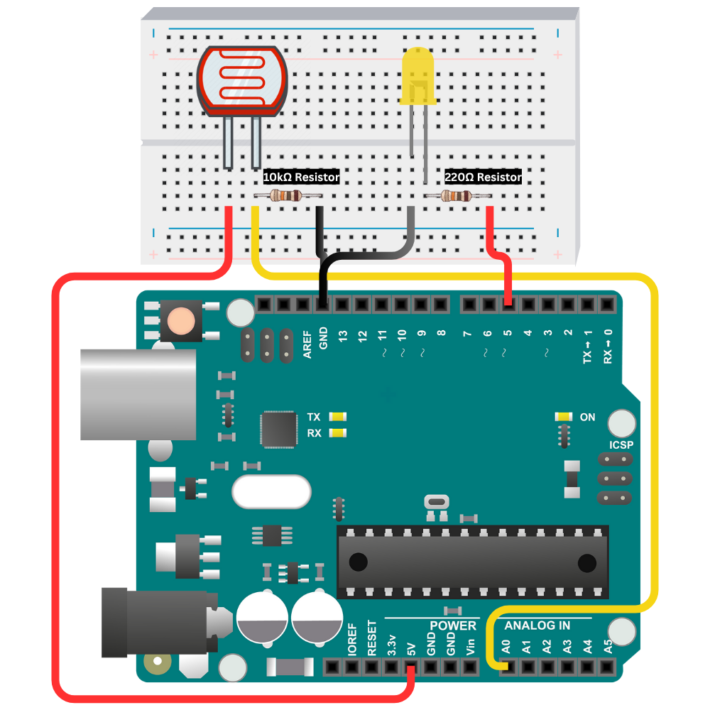
Circuit Wiring
(VCC) ---- [ LDR ] ----+---- [ 10kΩ Resistor ] ---- GND
                       |
                     (A0)
The point between the LDR and 10kΩ resistor connects to A0 (analog pin) of the Arduino.
- In bright light, the LDR has low resistance → higher voltage at A0.
- In dark, the LDR has high resistance → lower voltage at A0.
The LED is connected to pin D5, and its current is limited with a 220Ω resistor.
Circuit Diagram
Arduino Code
const int led = 5;
const int ldr = A0;

void setup() {
  pinMode(led, OUTPUT);
}

void loop() {
  int readLdr = analogRead(ldr);

  if (readLdr < 450) {
    digitalWrite(led, HIGH); // Turn on LED in dark
  } else {
    digitalWrite(led, LOW);  // Turn off LED in light
  }

  delay(200); // Small delay for stability
}
Code Breakdown
analogRead(ldr)reads the voltage at A0 (0–1023).if (readLdr < 450)checks if it’s dark (adjustable threshold).- LED is turned ON or OFF accordingly.
delay(200)prevents rapid switching (flicker).
Why 450 as threshold?
The threshold 450 was chosen based on experiment. If your ambient light is different (e.g., outdoors), adjust this value to fine-tune behavior. You can also open the Serial Monitor and print the readLdr value to better understand your environment:
Serial.begin(9600);
Serial.println(readLdr);
Common Issues & Fixes
LED Always ON or OFF?
- Your threshold may be too high or low. Try testing with your hand over the LDR.
Getting 0 in Serial Monitor?
- Make sure the LDR is wired correctly with the 10kΩ resistor as a divider.
LED flickers too much?
- Add hysteresis or increase the
delay()value slightly.
Real-World Applications
This basic LDR LED control concept can be expanded for:
- Night lamps that auto turn on when it's dark
- Solar panel trackers (with two LDRs)
- Light-activated security lights
- Ambient-controlled smart lighting
You can also control relays to switch on high-voltage appliances or use PWM for dimming effects.
Summary
You just built your first light-controlled Arduino system using an LDR. You:
- Learned how LDRs and voltage dividers work
- Wired a clean and functional circuit
- Wrote simple, effective code to control an LED
- Understood how to debug and calibrate the light sensor
This project is a stepping stone toward more advanced IoT or home automation systems. Keep experimenting!
Comments (0)
No comments yet. Be the first to comment!
Leave a Comment