How to Connect ESP32 with MAX30102: A Comprehensive Guide
Welcome to our step-by-step guide on connecting the powerful ESP32 microcontroller with the MAX30102 heart rate and pulse oximeter sensor. The MAX30102 is a sophisticated sensor capable of measuring heart rate and blood oxygen saturation (SpO2) by detecting light reflected from the skin. When paired with the ESP32, known for its robust Wi-Fi and Bluetooth capabilities, you can create advanced biomedical projects, from simple heart rate monitors to complex IoT health-tracking devices.
In this article, you will learn everything you need to know to get started, including the required components, how to wire the circuit, the complete code, and how to troubleshoot common issues.
Why This Project is Important
Monitoring vital signs like heart rate and SpO2 is crucial for health and fitness tracking. By interfacing the MAX30102 with an ESP32, you can:
- Build a personal, portable heart rate and SpO2 monitor.
- Log health data over time and send it to a web server or mobile app.
- Create an early-warning system for health-related issues.
- Develop innovative fitness gadgets that track your performance during workouts.
Components and Tools Required
Before we begin, gather all the necessary components and tools listed below:
- ESP32 Development Board: Any ESP32-based board will work.
- MAX30102 Sensor Module: A breakout board for the MAX30102 sensor.
- Breadboard: For creating a solderless circuit.
- Jumper Wires: To connect the components.
- Micro-USB Cable: To connect the ESP32 to your computer.
- Computer with Arduino IDE: You'll need the Arduino IDE to program the ESP32.
Circuit Diagram and Wiring
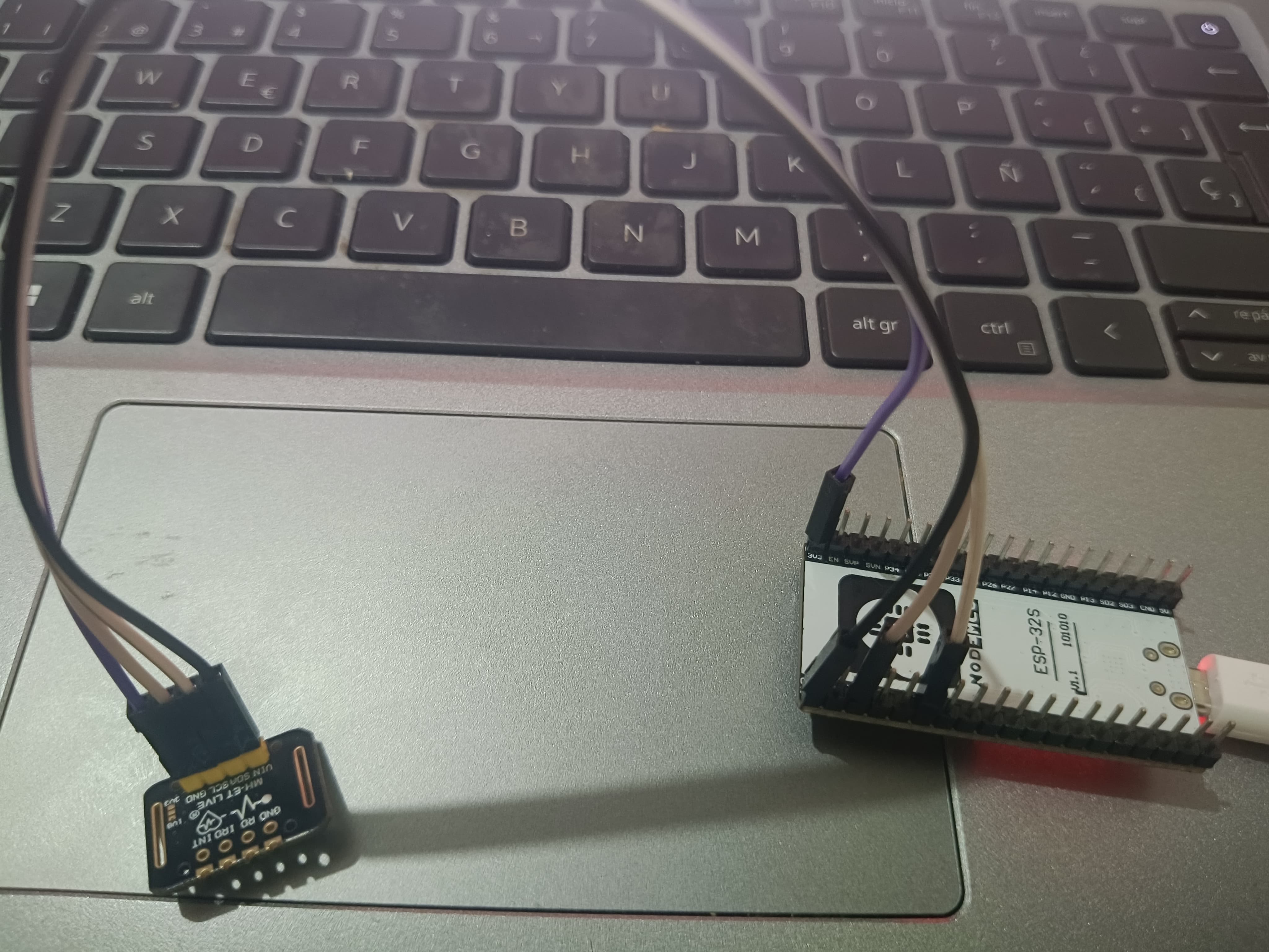
The connection between the ESP32 and the MAX30102 sensor is straightforward, as they communicate over the I2C protocol. Follow the wiring table and diagram below carefully.
| MAX30102 Pin | ESP32 Pin |
|---|---|
| VIN | 3V3 |
| GND | GND |
| SDA | GPIO 21 |
| SCL | GPIO 22 |
Here is a visual representation of the wiring:
Important: The MAX30102 sensor is a 3.3V device. Do not connect its VIN to the 5V pin of the ESP32, as this can permanently damage the sensor.
Setting Up the Arduino IDE
To program the ESP32, you need to configure the Arduino IDE and install the necessary libraries.
1. Install the ESP32 Board Manager
If you haven't already, add the ESP32 board manager to your Arduino IDE:
- Go to File > Preferences.
- In the "Additional Board Manager URLs" field, paste the following URL:
https://raw.githubusercontent.com/espressif/arduino-esp32/gh-pages/package_esp32_index.json - Go to Tools > Board > Boards Manager....
- Search for "esp32" and install the package by Espressif Systems.
2. Install the Required Libraries
We will use the SparkFun MAX3010x Pulse and Proximity Sensor Library, which is easy to use and works well with the MAX30102.
- Go to Tools > Manage Libraries....
- Search for "MAX30105" (the library is named after a similar sensor but supports the MAX30102).
- Install the library by SparkFun Electronics.
The Code
Here is the complete Arduino code for reading heart rate and SpO2 from the MAX30102 sensor. Copy this code into a new sketch in your Arduino IDE.
#include <Wire.h>
#include "MAX30105.h"
#include "heartRate.h"

MAX30105 particleSensor;

const byte RATE_SIZE = 4; // Increase this for more averaging. 4 is good.
byte rates[RATE_SIZE]; // Array of heart rates
byte rateSpot = 0;
long lastBeat = 0; // Time at which the last beat occurred

float beatsPerMinute;
int beatAvg;

void setup() {
  Serial.begin(115200);
  Serial.println("Initializing...");

  // Initialize sensor
  if (!particleSensor.begin(Wire, I2C_SPEED_FAST)) { // Use default I2C port, 400kHz speed
    Serial.println("MAX30102 was not found. Please check wiring/power.");
    while (1);
  }
  Serial.println("Place your finger on the sensor.");

  particleSensor.setup(); // Configure sensor with default settings
  particleSensor.setPulseAmplitudeRed(0x0A); // Turn Red LED to low to indicate sensor is running
  particleSensor.setPulseAmplitudeGreen(0); // Turn off Green LED
}

void loop() {
  long irValue = particleSensor.getIR();

  if (checkForBeat(irValue) == true) {
    // We sensed a beat!
    long delta = millis() - lastBeat;
    lastBeat = millis();

    beatsPerMinute = 60 / (delta / 1000.0);

    if (beatsPerMinute < 255 && beatsPerMinute > 20) {
      rates[rateSpot++] = (byte)beatsPerMinute; // Store this reading in the array
      rateSpot %= RATE_SIZE; // Wrap variable

      // Take average of readings
      beatAvg = 0;
      for (byte x = 0 ; x < RATE_SIZE ; x++)
        beatAvg += rates[x];
      beatAvg /= RATE_SIZE;
    }
  }

  if (irValue < 50000) {
    // If IR value is low, it means no finger is on the sensor
    Serial.println(" No finger?");
    beatAvg = 0; // Reset average
  }

  // Print the results
  Serial.print("IR=");
  Serial.print(irValue);
  Serial.print(", BPM=");
  Serial.print(beatsPerMinute);
  Serial.print(", Avg BPM=");
  Serial.print(beatAvg);

  Serial.println();
}
Code Explanation
- Includes: We include the
Wire.hlibrary for I2C communication,MAX30105.hfor the sensor, andheartRate.hfor the beat detection algorithm. - setup(): This function initializes the Serial Monitor and the MAX30102 sensor. It checks if the sensor is connected correctly and configures it with default settings.
- loop(): The main loop continuously reads the infrared (IR) light value from the sensor. The
checkForBeat()function from the library analyzes this value to detect a heartbeat. When a beat is detected, it calculates the beats per minute (BPM) and updates a running average to provide a more stable reading.
Uploading and Testing
- Connect your ESP32 to the computer.
- Go to Tools > Board and select your ESP32 board model.
- Select the correct Port.
- Click the Upload button.
- Once the code is uploaded, open the Serial Monitor (Tools > Serial Monitor) and set the baud rate to 115200.
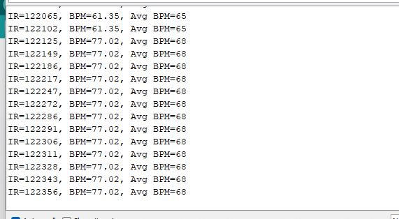
- Place your finger gently on the sensor. You should start seeing the IR values and the calculated BPM on the Serial Monitor.
For a more visual representation, you can use the Serial Plotter (Tools > Serial Plotter) to see the IR signal and BPM in real-time.
How it Works: A Deeper Dive
The MAX30102 sensor works based on the principle of photoplethysmography (PPG). It has two LEDs—one red and one infrared—and a photodetector.
- Heart Rate: Deoxygenated hemoglobin in the blood absorbs more infrared light. As blood pulses through your finger, the amount of reflected IR light changes. The sensor detects these changes, and the algorithm calculates the heart rate.
- SpO2: The sensor measures the difference in absorption between red and infrared light. Oxygenated blood absorbs more infrared light and allows more red light to pass through, while deoxygenated blood does the opposite. By comparing the ratios of reflected light, the sensor can estimate the oxygen saturation level in your blood.
Troubleshooting Common Issues
- "MAX30102 was not found.": This is the most common error.
- Check your wiring: Ensure SDA and SCL lines are not swapped and are connected to GPIO 21 and 22 respectively.
- Check power: Make sure the sensor is powered by the 3.3V pin.
- Check connections: A loose jumper wire on the breadboard can cause this issue.
- Inaccurate or "0" BPM readings:
- Finger placement: Apply gentle, consistent pressure. Pressing too hard can restrict blood flow and affect readings.
- Ambient light: Too much ambient light can interfere with the sensor. Try to shield the sensor from bright lights.
- Movement: Stay still while taking a measurement, as movement can create noise in the signal.
Conclusion
Congratulations! You have successfully connected a MAX30102 sensor to an ESP32 and can now read your own heart rate. This project serves as an excellent foundation for more advanced applications. You could now try to display the data on an OLED screen, send it to a mobile app via Bluetooth, or log it to a cloud server using Wi-Fi.
We hope this guide was helpful. Feel free to leave a comment if you have any questions or share your project with us!
Frequently Asked Questions (FAQ)
Q1: Can I use different GPIO pins for I2C on the ESP32? A1: Yes, the ESP32's I2C pins are configurable. You can define custom SDA and SCL pins by using Wire.begin(SDA_PIN, SCL_PIN) in your setup function. However, GPIO 21 and 22 are the default and recommended pins.
Q2: How accurate is the MAX30102 sensor? A2: The MAX30102 is a high-quality sensor, but it is not a medical-grade device. Its accuracy can be affected by factors like skin tone, finger placement, and motion. For casual health and fitness tracking, it is quite reliable.
Q3: Can this project measure blood pressure? A3: No, the MAX30102 sensor is not capable of measuring blood pressure. Blood pressure measurement requires different types of sensors and techniques.
Comments (0)
No comments yet. Be the first to comment!
Leave a Comment