How to Build a 2.4GHz Scanner with Arduino and NRF24L01
How to Build a 2.4GHz Scanner with Arduino and NRF24L01
Date Published: July 3, 2025 Last Updated: July 3, 2025
Introduction
While the NRF24L01 is typically used in pairs for communication, a single module can be turned into a powerful diagnostic tool. With one Arduino and one NRF24L01, you can build a 2.4GHz scanner to detect wireless traffic around you. This is useful for troubleshooting, finding a clear channel for your projects, and learning about the radio frequency environment.
Components and Tools Required
To get started with this project, you will need the following components:
- 1 x Arduino Board (e.g., Arduino Uno, Nano)
- 1 x NRF24L01 Module
- 1 x NRF24L01 Adapter Module (Optional, but highly recommended for stable 3.3V power)
- Jumper Wires
- 1 x USB Cable for programming the Arduino
Circuit Wiring Steps
The NRF24L01 module communicates with the Arduino using the SPI protocol.
Important: The NRF24L01 module requires a 3.3V power supply. Connecting it to the 5V pin of the Arduino will permanently damage the module. If you are not using an adapter, connect the VCC pin to the 3.3V output on your Arduino.
Here is the pinout for connecting the NRF24L01 to an Arduino Uno/Nano:
| NRF24L01 Pin | Arduino Uno/Nano Pin |
|---|---|
| GND | GND |
| VCC | 3.3V |
| CE | 9 |
| CSN | 10 |
| SCK | 13 |
| MOSI | 11 |
| MISO | 12 |
| IRQ | (Not Connected) |
Scanner Code Explanation
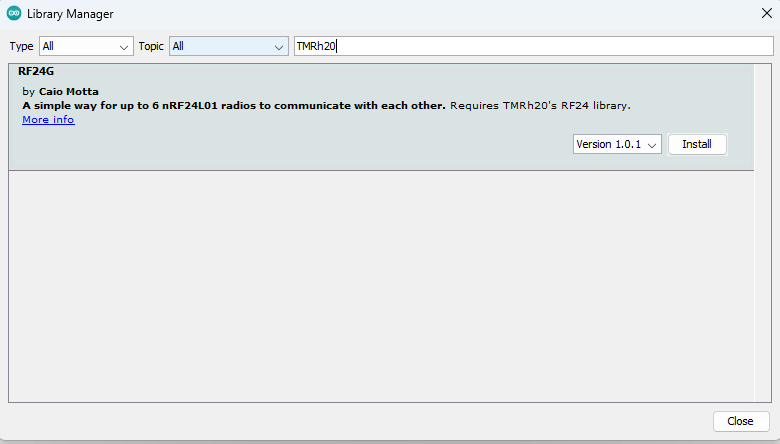
For this project, we will use the RF24 library by TMRh20. You can install this library through the Arduino IDE's Library Manager (Sketch > Include Library > Manage Libraries...).
This code will cycle through all 125 available channels, listen for a brief moment on each, and then print a value representing the signal strength it detected.
#include <SPI.h>
#include <nRF24L01.h>
#include <RF24.h>

// Create an RF24 object
RF24 radio(9, 10); // CE, CSN

const int num_channels = 126;
int values[num_channels];

void setup() {
  Serial.begin(9600);
  Serial.println("Starting NRF24L01 Channel Scanner...");

  radio.begin();
  radio.setAutoAck(false);

  // Start on channel 0
  radio.setChannel(0);

  // Set the power level to the minimum
  radio.setPALevel(RF24_PA_MIN);

  // Use a data rate of 250kbps to be more sensitive
  radio.setDataRate(RF24_250KBPS);

  Serial.println("Scan starting... Output is a single hex character (0-F).");
  Serial.println("Higher values mean more noise/activity on that channel.");
}

void loop() {
  // Clear the values array
  memset(values, 0, sizeof(values));

  // Scan all channels
  for (int i = 0; i < num_channels; i++) {
    radio.setChannel(i);
    radio.startListening();
    delayMicroseconds(128);
    radio.stopListening();
    if (radio.testCarrier()) {
      values[i]++;
    }
  }

  // Print out the results
  for (int i = 0; i < num_channels; i++) {
    Serial.print(values[i], HEX);
  }
  Serial.println();

  delay(1000);
}
Expected Outcome
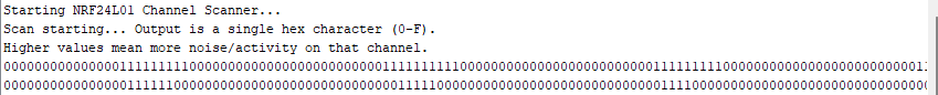
After uploading the code, open the Arduino IDE's Serial Monitor (set to 9600 baud). You will see a long string of hexadecimal characters (0-F) printed every second. Each character represents a channel, from 0 to 125.
- A
0means the channel is likely clear. - A higher value (like
A,C, orF) indicates significant activity or interference on that channel, likely from Wi-Fi, Bluetooth, or other 2.4GHz devices.
Troubleshooting & Advanced Tips
- No Output or Gibberish: Double-check your wiring. A single loose wire is the most common issue. Ensure the Serial Monitor is set to the correct baud rate (9600).
- Power Issues: If the scanner is unreliable, the NRF24L01 might not be getting stable power. Try adding a 10µF capacitor across the VCC and GND pins of the module. Using the adapter module is the best way to prevent power issues.
- Interpreting the Results: Wi-Fi routers typically operate on channels that correspond to specific ranges in the NRF24L01's scan. You will likely see high activity around channels used by your home Wi-Fi.
Summary
Congratulations! You have successfully built a 2.4GHz scanner with a single NRF24L01 module. This tool can help you diagnose wireless issues and choose the best channel for your future wireless projects to avoid interference.
Frequently Asked Questions (FAQ)
Question 1: Why do I see so much activity on certain channels? Answer 1: The 2.4GHz band is very crowded. It's used by Wi-Fi, Bluetooth, cordless phones, and other devices. The scanner is picking up all of this traffic. You'll likely see peaks of activity corresponding to the channels your Wi-Fi router is using.
Question 2: How do I choose a "good" channel for a project? Answer 2: Look for a range of channels where the scanner consistently outputs 0 or very low numbers. These are the quietest channels in your environment and will provide the most reliable communication for your projects.
Question 3: Can this scanner decode the data it detects? Answer 3: No, this simple scanner only detects the presence of a signal (a "carrier wave"). It does not decode the data being transmitted.
Comments (0)
No comments yet. Be the first to comment!
Leave a Comment