Getting Started with the ESP32-CAM: A Beginner's Guide
Welcome to your complete guide to the ESP32-CAM! This small but powerful microcontroller comes with a built-in camera, a microSD card slot, and Wi-Fi capabilities, making it the perfect choice for projects like DIY security cameras, bird watchers, and other remote monitoring systems.
By the end of this tutorial, you will have learned how to set up your programming environment, connect the hardware, and deploy a fully functional video streaming web server. Let's get started!
Part 1: Components and Tools Required
To follow this guide, you will need a few key pieces of hardware and software.
Hardware:
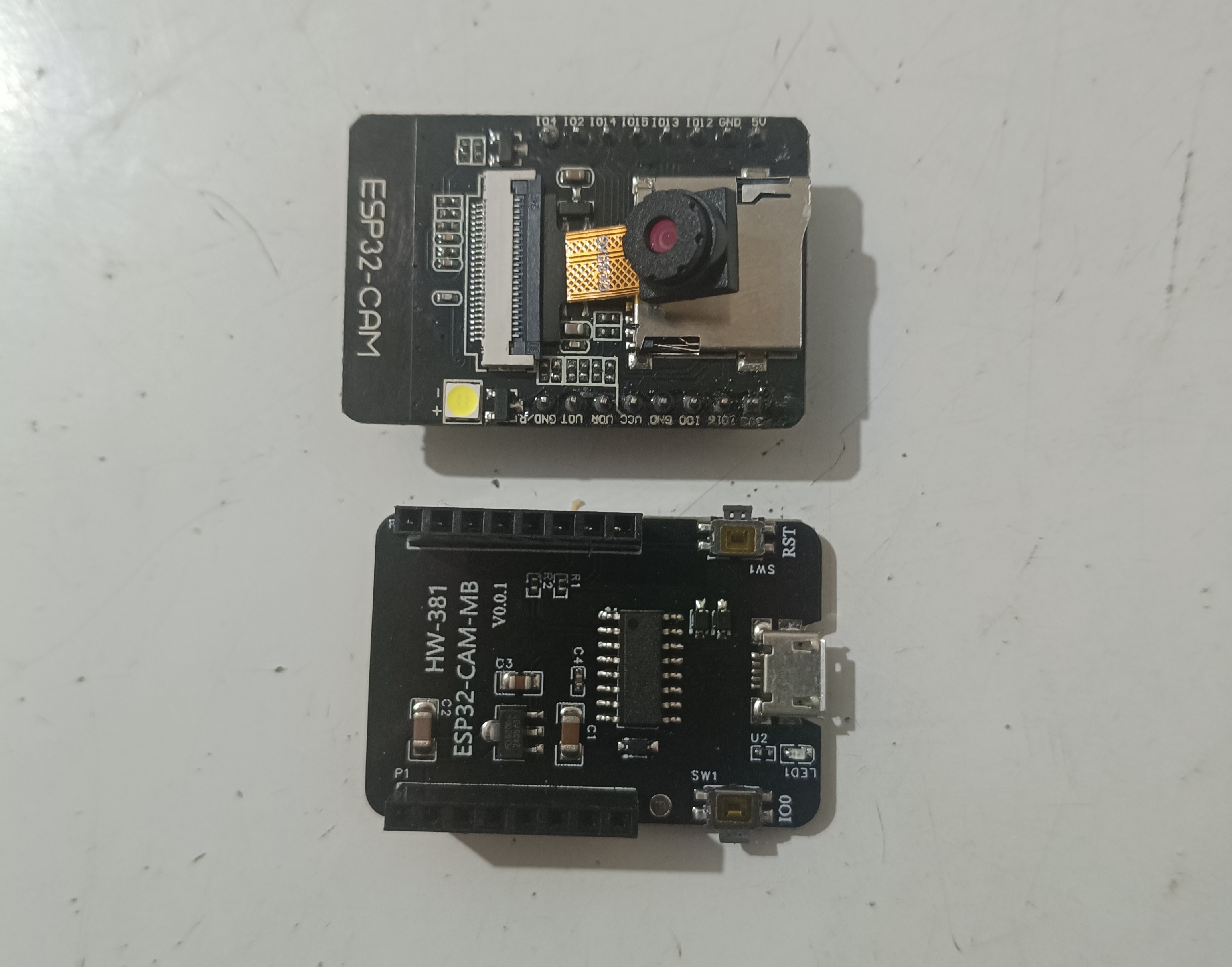
- An ESP32-CAM Board: Make sure it's the model with the camera module (usually the OV2640).
- USB to TTL Serial Programmer: This is essential for programming the ESP32-CAM. These come with various USB connectors (Mini-USB, Micro-USB, etc.) and chipsets (FTDI, CP2102, CH340). Any 5V/3.3V compatible programmer will work perfectly.
- Jumper Wires: A set of male-to-female DuPont jumper wires.
- A 5V Power Supply (Optional but Recommended): While the programmer can supply power, the ESP32-CAM can be power-hungry, especially when Wi-Fi is active. A stable external 5V power supply (at least 2A) is recommended for reliable operation.
- A USB Cable: To connect your specific programmer to your computer.
Software:
- Arduino IDE: The latest version, which can be downloaded for free from the official Arduino website.
Part 2: Setting Up Your Arduino IDE
Before you can program the board, you need to teach the Arduino IDE how to recognize the ESP32.
1. Add the ESP32 Board Manager URL
- Open the Arduino IDE.
- Go to File > Preferences (on Windows) or Arduino > Settings (on macOS).
In the "Additional boards manager URLs" field, paste the following URL:
https://raw.githubusercontent.com/espressif/arduino-esp32/gh-pages/package_esp32_index.json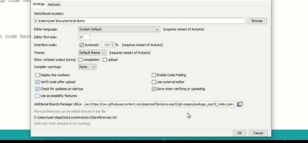
- Click OK.
2. Install the ESP32 Board Package
- Go to Tools > Board > Boards Manager...
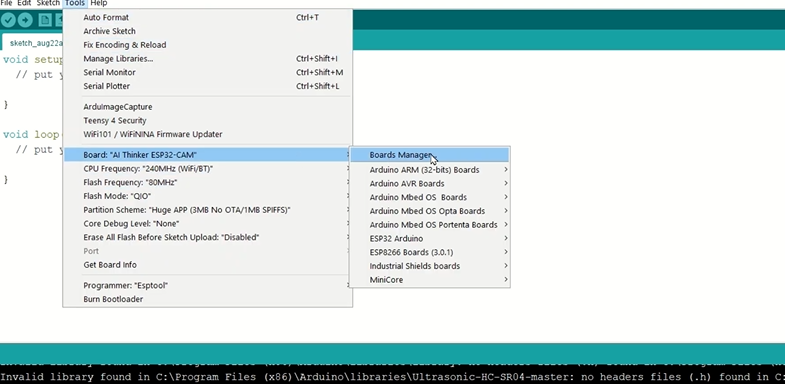
- In the search bar, type
esp32. - The "esp32 by Espressif Systems" package will appear. Click the Install button. This will take a few minutes to download and install.
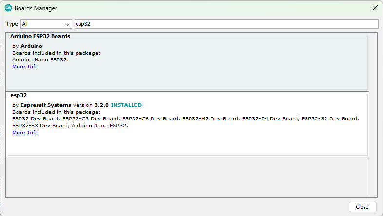
- Once it's finished, close the Boards Manager.
Part 3: Connecting the Hardware (The Critical Step!)
This is where many beginners run into trouble. Follow these wiring connections carefully. Even if your programmer has a Micro-USB port, the pin labels (GND, VCC, TX, RX) will be the same.
Important: The key to programming the ESP32-CAM is to connect the GPIO 0 pin to GND. This puts the board into "flashing mode."
| Programmer Pin | ESP32-CAM Pin |
|---|---|
| GND | GND |
| VCC (5V) | 5V |
| TX | U0R (RX) |
| RX | U0T (TX) |
| (No Connection) | 3V3 |
Additionally, for flashing mode:
- Connect GPIO 0 on the ESP32-CAM directly to GND.
A visual representation of the connections listed above.
Part 4: Programming the ESP32-CAM
We will use the built-in example code to create a video streaming web server.
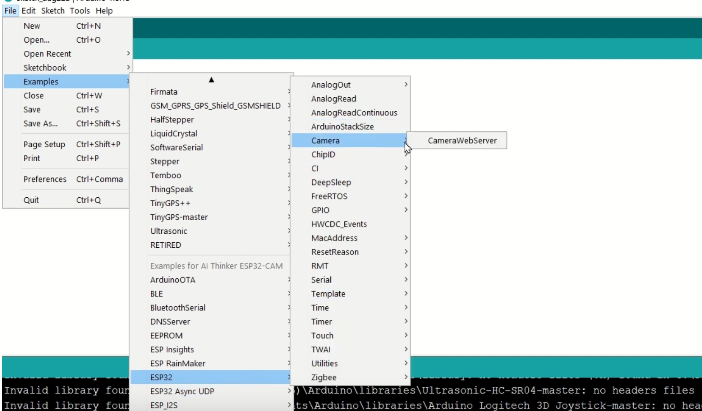
1. Open the Example Sketch
- In the Arduino IDE, go to File > Examples > ESP32 > Camera and select CameraWebServer.
2. Configure the Code
- In the code that opens, you need to make two changes:
Select the Camera Model: Uncomment the line for the
CAMERA_MODEL_AI_THINKER.// #define CAMERA_MODEL_WROVER_KIT // #define CAMERA_MODEL_ESP_EYE // #define CAMERA_MODEL_M5STACK_PSRAM // #define CAMERA_MODEL_M5STACK_V2_PSRAM // #define CAMERA_MODEL_M5STACK_WIDE // #define CAMERA_MODEL_M5STACK_ESP32CAM // #define CAMERA_MODEL_TTGO_T_JOURNAL #define CAMERA_MODEL_AI_THINKER // This is the one you want!Enter Your Wi-Fi Credentials: Find the following lines and replace the placeholders with your Wi-Fi network's name (SSID) and password.
const char* ssid = "YOUR_WIFI_SSID";
const char* password = "YOUR_WIFI_PASSWORD";
3. Upload the Code
- Go to Tools > Board > ESP32 Arduino and select AI Thinker ESP32-CAM.
- Select the correct Port from the Tools menu. This is the port your programmer is connected to.
- Ensure GPIO 0 is connected to GND.
- Click the Upload button (the right-arrow icon).
- Watch the console at the bottom of the IDE. When you see the message
Connecting........_____....._____, press the onboard RST (Reset) button on the ESP32-CAM once. - The code should now compile and upload.
Part 5: Accessing Your Video Stream
Once the upload is complete, you're ready to see the results!
- IMPORTANT: First, disconnect the GPIO 0 wire from GND. The board will not boot correctly if it's still in flashing mode.
- Press the RST button again to restart the board in normal mode.
- Open the Serial Monitor in the Arduino IDE (the magnifying glass icon in the top right).
- Set the baud rate to 115200.
You will see the board connect to your Wi-Fi network and then print out its IP address, like this:
Camera Ready! Use 'http://192.168.11.120' to connect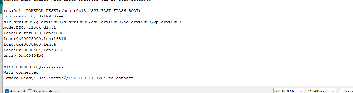
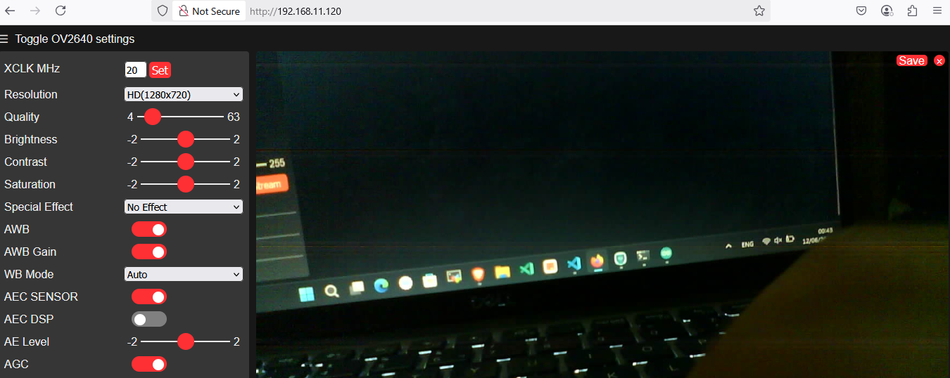
- Open a web browser on a device connected to the same Wi-Fi network and enter the IP address shown.
- You should now see a web page with camera controls. Click Start Stream to see the live video feed from your ESP32-CAM!
Troubleshooting Common Issues
- Error: "Failed to connect to ESP32: Timed out waiting for packet header"
- This is the most common error. It means the board isn't in flashing mode. Double-check that GPIO 0 is firmly connected to GND before you press upload, and make sure to press the RST button at the correct time. Also, verify that your RX and TX lines are not swapped.
- Brownout Detector was Triggered
- This error in the Serial Monitor means the board is not getting enough power. Use a dedicated 5V 2A power supply instead of relying on the programmer.
- Camera Init Failed
- This can also be a power issue. Ensure you're providing stable 5V power. Also, check that you have selected the correct
CAMERA_MODEL_AI_THINKERin the code.
- This can also be a power issue. Ensure you're providing stable 5V power. Also, check that you have selected the correct
Conclusion & Next Steps
Congratulations! You have successfully set up your ESP32-CAM and are streaming live video over Wi-Fi. You now have the foundational skills to build more complex projects.
From here, you could try:
- Integrating a PIR motion sensor to start recording when motion is detected.
- Saving images and videos to a microSD card.
- Exploring the different camera settings in the web interface to improve image quality.
Comments (0)
No comments yet. Be the first to comment!
Leave a Comment