Control an LED with an Arduino Button Press: A Beginner's Guide

Introduction
Have you ever wanted to bring your electronics projects to life with interactive controls? This guide will show you one of the fundamental building blocks of digital making: how to use a pushbutton to control an LED with an Arduino. In just a few simple steps, you'll learn how to build a circuit and write the code to turn an LED on and off with the single press of a button.
This tutorial is perfect for beginners and will give you a solid foundation for more complex Arduino projects. By the end, you will have a working circuit and a clear understanding of how to handle digital inputs and outputs.
Components and Tools Required
Before we start, let's gather all the necessary components and tools. You won't need much to get this project up and running.
Hardware:
- 1 x Arduino Uno (or any other Arduino board)
- 1 x Breadboard
- 1 x LED (any color)
- 1 x 220 Ohm Resistor
- 1 x 10k Ohm Resistor
- 1 x Pushbutton
- Jumper Wires
Software:
- Arduino IDE (Integrated Development Environment)
Circuit Wiring Steps
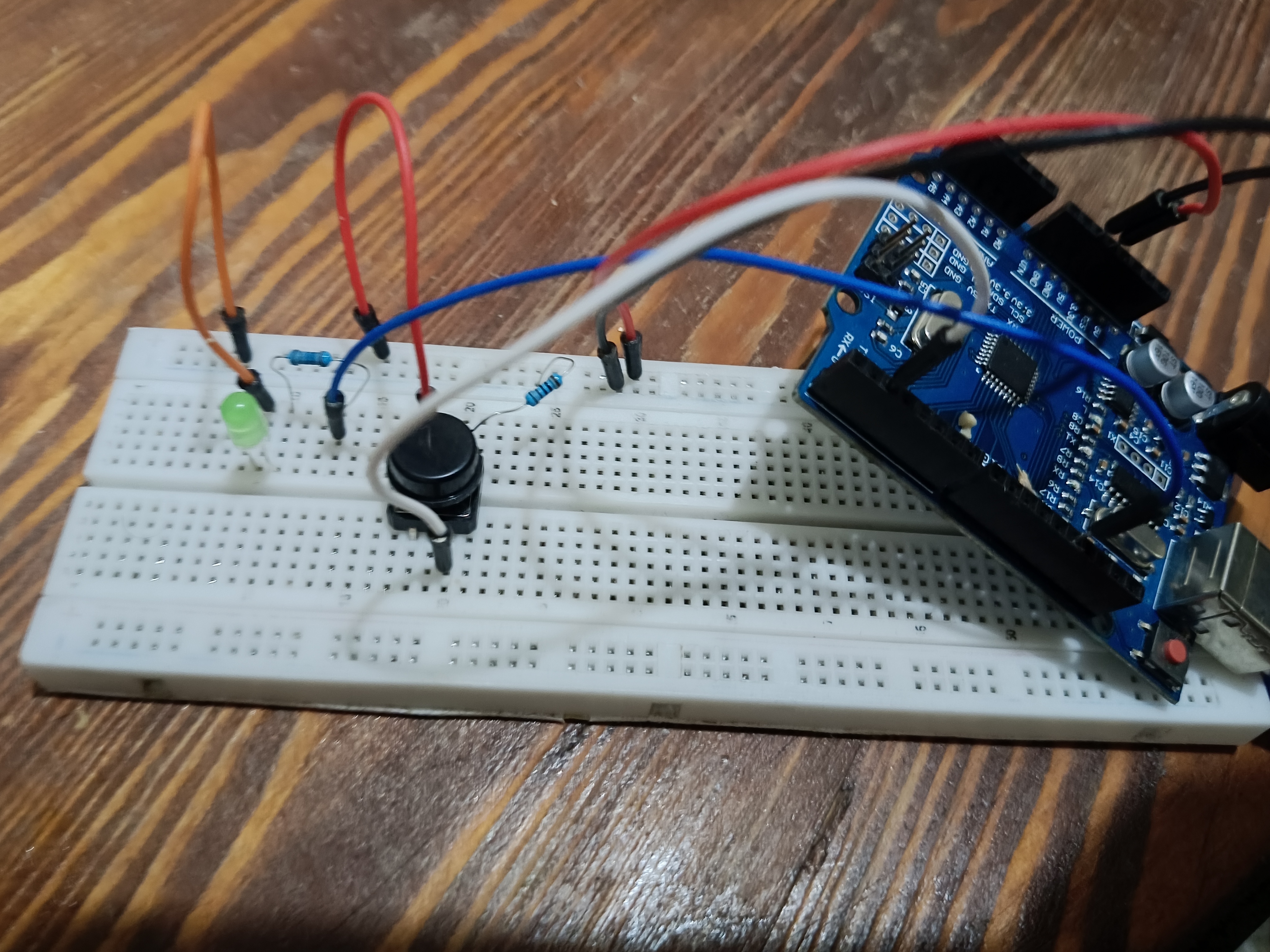
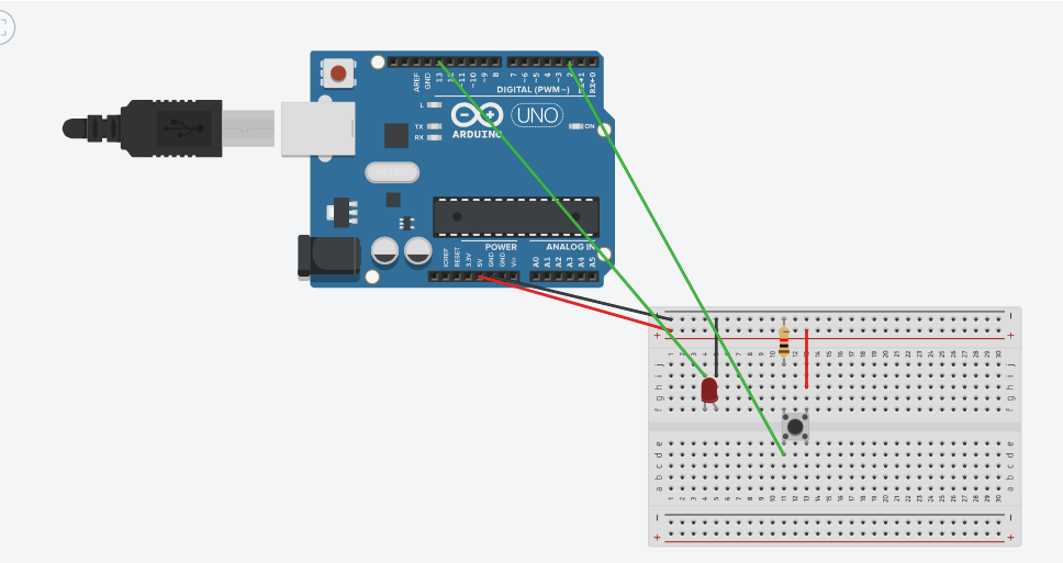
Connect your components carefully as follows:
LED:
- Anode (Longer Leg) → 220 Ohm Resistor → Arduino Digital Pin 13
- Cathode (Shorter Leg) → Arduino GND
Pushbutton:
- One Leg → Arduino 5V
- Opposite Leg → Arduino Digital Pin 2
- Same Leg as Pin 2 → 10k Ohm Resistor → Arduino GND

The Arduino Code
Now it's time to upload the code to your Arduino. This sketch will read the state of the button and toggle the LED accordingly.
// Define the pin numbers for the button and LED
const int buttonPin = 2;
const int ledPin = 13;

// Variable to store the current state of the button
int buttonState = 0;
// Variable to store the last known state of the button
int lastButtonState = 0;
// Variable to store the state of the LED
boolean ledOn = false;

void setup() {
  // Initialize the LED pin as an output
  pinMode(ledPin, OUTPUT);
  // Initialize the button pin as an input
  pinMode(buttonPin, INPUT);
  // Start serial communication
  Serial.begin(9600);
}

void loop() {
  // Read the current state of the button
  buttonState = digitalRead(buttonPin);

  // Check if the button state has changed
  if (buttonState != lastButtonState) {
    if (buttonState == HIGH) {
      // If the button is pressed, toggle the LED state
      ledOn = !ledOn;

      // Log button press
      Serial.println("Button pressed. LED toggled.");
    }
  }
  // Save the current button state for the next loop
  lastButtonState = buttonState;

  // Set the LED to the new state
  digitalWrite(ledPin, ledOn ? HIGH : LOW);

  // A small delay to help with button debouncing
  delay(50);
}
Code Explanation
const int buttonPin = 2;andconst int ledPin = 13;: These lines assign the hardware pins to constant variables for easier reference.buttonStateandlastButtonState: These variables are essential for detecting a change in the button's state (from not pressed to pressed).ledOn: This boolean variable keeps track of whether the LED should be on or off.pinMode(): In thesetup()function, we configure theledPinas anOUTPUTand thebuttonPinas anINPUT.digitalRead(): In theloop()function, this reads the voltage at thebuttonPin. It will beHIGHwhen the button is pressed andLOWotherwise.digitalWrite(): This function is used to turn the LED on (HIGH) or off (LOW).ledOn = !ledOn;: This is the core logic. Each time a button press is detected, this line inverts the value ofledOn(true becomes false, and false becomes true).
How It Works
Once the code is uploaded, your circuit is ready! Press the pushbutton. The LED should turn on. Press it again, and the LED will turn off. Each press toggles the state of the LED.
This simple project is a fantastic introduction to digital inputs and outputs on the Arduino. The principles you've learned here—reading a button press and controlling an output—are fundamental to countless electronics projects.
Troubleshooting Tips
Encountering issues? Here are a few common problems and their solutions:
- LED doesn't turn on:
- Check that the LED is inserted correctly. The longer leg (anode) should be connected to the resistor and the Arduino pin, and the shorter leg (cathode) to ground.
- Ensure all your wiring connections are secure.
- LED is always on or off:
- Make sure the 10k Ohm pulldown resistor is connected correctly. Without it, the input pin can "float," leading to unpredictable behavior.
- LED flickers erratically when the button is pressed:
- This is due to "bouncing," where the button contacts bounce when pressed. The small
delay(50);in the code helps to mitigate this.
- This is due to "bouncing," where the button contacts bounce when pressed. The small
Conclusion
Congratulations! You have successfully built a circuit that uses an Arduino and a button to control an LED. You've learned how to wire the components on a breadboard and how to write a simple yet effective Arduino sketch to control the circuit's logic. This project is a stepping stone to more advanced and exciting electronic creations.
We encourage you to experiment further. Try adding more LEDs or using different types of switches!
Feel free to leave a comment below if you have any questions or share this article with fellow makers on social media. Also, for your next project, check out our guide on creating a fading LED effect.
Comments (0)
No comments yet. Be the first to comment!
Leave a Comment